Monday, December 27, 2010

base improvements


After last week's dry run with the whole frame assembled, I decided that the altitude bearing wasn't light enough. I decided to buy a couple of track rollers from McMaster, along with brass threaded inserts, and installed them in the central beam of the base. I'm glad I did, because this modification makes it almost as easy to adjust the altitude as the azimuth. I can kind of adjust how much weight sits on the teflon pads by shimming them with washers, although it's not especially convenient to do this.


I also built the tripod-ish base that the azimuth bearing attaches to. Nothing too fancy there. The whole height of the base is a little on the tall side, but still not enough to require anything more than a step stool to use when viewing.

Monday, December 20, 2010

nearly-complete frame


Well, despite the lack of posts from the last month, I've continued to tinker away on the scope and now have it in a form that pretty strongly resembles the final product.


For starters I painted everything. Rather, I used a black gloss stain-plus-polyurethane product from Minwax called Polywax to varnish all of the wood components. This is nice because it preserves a little of the grain, which is attractive. Although technically an indoor stain, the polyurethane should keep everything waterproof to the degree that I will need it to be.


I had to bisect the trunions, in order to allow the scope to collapse down to a portable size. I had to buy two 8" strap hinges made by Stanley to allow the trunions to bend in the middle and fold back on themselves. I also bought two somewhat heavy-duty draw-latches from McMaster-Carr to attach to the inside to secure the trunions in their extended position while viewing.


The bisected trunion design actually presents some significant design dillemmas. First, the strap hinges are not load rated, and there is what looks like a plastic washer in the hinge which prevents metal-metal contact. This plastic washer could be the site of failure, depending on just how much compressive force it can take. For now, though, it seems to be able to hold the full weight of the optical tube as I've been testing it. I had no way of knowing this at the outset, though, so this caused me much consternation when I was trying to choose what type of hinge to buy. Regardless, I am happy with these. I would still rather have the torque applied across the 16" span of the hinge, even with its plastic washer, than have it exclusively borne by the wooden trunions.

The second dillemma is that the extended portions of the trunions flex a small amount, despite being secured with the draw-latches. I still have to make a cross bar to hold the trunions the appropriate distance apart. While not difficult, this is still another piece of the scope that I'll have to set up prior to viewing. Also, it was surprisingly hard to find the tube-connecting nuts that I'm using for this bar. These nuts look like the plastic things on the end of ski poles, but they are made of metal and have a nut in the middle. You jam them in the end of a tube and they stay there and let you thread a bolt in parallel to the tube. Very useful, but not a single hardware store clerk in all of Seattle had ever heard of them.

All in all, the trunion issues makes me reconsider the ultra-compact design. Oh well, I can always build a classical mirror box in the future!

Next, I made the altitude bearings. I bought a 1/4" thick 6" x 6" teflon pad from onlinemetals.com. I sliced this into four 3" x 3/4" sized pads, and secured them to the base with flat head screws. The pads are about 20" apart on the base, which makes for a nice wide margin of error. If the center of gravity moves outside the pads when rotating the scope, it will tip over. So it's nice to have a relatively large margin of error, even though I think my estimate of the CG location is actually pretty accurate.


I then bought a couple of cheap vinyl wall-base panels, which I sliced into 3/4" x 20*pi/2" strips. I epoxied these strips to the trunions, using a Loc-tite gel-epoxy product that seemed to work well. I don't know the precise coefficient of friction between vinyl and teflon, and I think melamine-teflon may have it beat, since that is what is recommended in K&B. However, I couldn't find any melamine laminate, and I don't think it could be that dramatically different anyway.

That said, in my current design, the friction of the altitude bearing is significantly greater than that of the azimuth bearing, which, again, is a ball-bearing containing lazy-susan from McMaster. There are reasons why this may be nice. Tipping over is a significant risk, and is more likely if altitude bearings let the tube descend too quickly. Plus, at high latitudes such as Seattle (47 deg north), the azimuth bearing is more closely aligned with the Earth's axis than the altitude bearings are. When tracking objects as the Earth rotates, it's therefore more important to have an easy azimuth bearing. Again, that only applies at high latitudes. The opposite would be true at the equator, and as for San Diego (32 deg north), one would probably want both bearings to be easy! For that reason, I will probably purchase some track rollers from McMaster to use for the altitude bearings.


I finally drilled the truss tubes to secure the tube adapters in place. I will have to do this again after shortening the tubes when I know the exact focal length of the mirror. The whole optical tube is very rigid now.


That's most of the frame of the telescope. I still have have to make a tripod for the azimuth bearing to sit on, as well as the trunion strut, but these are pretty simple to do. I'll post about the optics next, but suffice it to say for now that the primary mirror has been commissioned!

Sunday, November 7, 2010

trunions & base


I made some progress on the trunions and base this week (ie, the altitude and azimuth bearings). I'm still waiting for a couple of components from McMaster-Carr to get here before they will be complete.

The trunions are two large arcs of 13-ply wood. They are positioned so that their center is 14 inches above the mirror surface, which is approximately where the center of gravity of the optical tube will be. This makes the mount points of the mirror cell 17 inches from the center, and so I made the inner and outer radii of the trunions 14 and 20 inches respectively. Hopefully this thickness will be sufficient to support the 60 lb optical tube - if not I may need to add some aluminum struts. I will eventually need to put a hinge and latch in the middle of each trunion, since there's no way this would fit into my car at the present time. This issue makes me debate the merits of an "ultra-compact" design without a dedicated mirror box, vs the more traditional Dobsonian design, but I still think I'm happier this way.

The base is a a relatively simple palette-like structure, using the complementary pieces of plywood left over from making the trunions, held together with framing lumber 2x4's. It will eventually sit on a lazy-Susan turntable from McM-C, en route currently. The footprint of the base is 24 x 28 inches.

At some point, I need to buy the teflon pads and plastic molding that makes the altitude bearing smooth to maneuver.

Sunday, October 24, 2010

truss tube & focuser board

Several components for the truss tube and focuser have arrived. Here they are assembled:


I connected the truss tube to the mirror cell with three blocks of wood of dimension 1.5 x 2.5 x 3.5", cut right from a two-by-four (a misnomer, two-by-four's are actually 1.5 x 3.5"), and bolted to the mirror cell at a radius of 9" very close to 120 degrees apart. The inner diameter of the blocks is 8.25" which allows them to serve as bumpers for the mirror if it slides around accidentally. The blank in the photos is a 16.5" diameter piece of plywood left over from making the secondary ring, and fits nicely between the blocks. I still need to stabilize the blocks on the mirror cell, since now they are prone to rotating a little around the central bolt. I may do this by routing a pattern into the bottom so they will fit snugly on the metal frame.


I mounted three ball-and-socket joints from MoonLite Telescope Accessories (MTA) to the wooden blocks, and another three to the secondary cage ring. These joints greatly simplify the design of the whole telescope, since they make the complex angles of the truss tube possible, are are easy to dis/assemble. The tubes themselves are aluminum, 1.25" in outer diameter, 0.05 thick, and are also from MTA. "Do you know what the @#$% you can do with an aluminum tube?"


The distance from the mirror center to the ball-and-socket joint seats is approximately 10.4", and they are about 7.58 degrees apart at that distance. This makes the truss intrusion 8.55", just larger than the aperture of the secondary cage. By truss intrusion, I mean the distance of the truss tube to mirror center at its closest in projection. Picture a hexagon inscribed in a circle - the midpoints of the sides of the hexagon are closer to the center of the circle than the vertices of the hexagon are.

Right now the tubes are all 6' in length, but I will shorten them by about 1' after I order the mirror. I am planning to buy a 16" f/4.5 mirror but the exact focal length has to be measured after fabrication, so I won't chop the tubes until then. I also need to drill the tube caps to seat them a little more securely.

I also made a focuser board, dimension 6 x 8", with a 2 & 3/8" diameter hole centered at 5 inches from the end. The board made is 13-ply "import birch" 3/4" plywood from Dunn Lumber, same as the secondary ring. It will eventually hold the MTA focuser I bought, but I haven't attached it yet. I'm waiting until the spider and mirror holder arrive before I do any more with the focuser board. I've ordered these from astrosystems.biz and they should be here in a couple of weeks.


The fasteners for these components are (mostly) all from McMaster-Carr, which I again will recommend for their extensive but easily navigable catalog.

The assembled truss tube and focuser board have a very light but rigid feel. I am eager to see how things improve after the two improvements to the wooden blocks and tube caps that I mentioned. After I install the spider/secondary mirror holder, I will probably be able to get a good estimate of the weight of the entire secondary cage, which I need to calculate the diameter of the trunions that I will build next!

Tuesday, October 5, 2010

secondary cage

At peril to both my relationship and, no doubt, my lease, I have completed the secondary cage ring, shown below, in my wood-shop/living room. I'm planning on just a single ring, hopefully that will suffice for rigidity and focuser board stability.

Friday, October 1, 2010

mirror cell design

It turns out that a lot of work has been done comparing the "equal area/weight" method for mirror cell design to more complex methods based on finite element analysis. In particular a program PLOP has been developed by David Lewis, and some results are given here. In general, the results reassure me that the 37.6% and 80.5% radii, which are from Kriege & Barry and which I used for my 16" scope, are within the range of values arrived at by various combinations of mirror thickness and secondary obstruction parameters. The chief difference is that their radii are skewed outwards a little bit by the assumption that flexion of the obscured central portion of the mirror can be disregarded; however, the difference is not large. Plus, they suggest that 9 points would suffice for a 16" mirror, so my 18 point cell be over-engineered anyway. Phew!

Tuesday, September 28, 2010

float

The parts of the float are done! Thanks Ballard Sheet Metal and onlinemetals.com (also, incidentally, located in Ballard). I should also mention McMaster-Carr, encyclopedic but pricy online source of almost anything mechanical, in particular, the collimation bolts I'm using. Fortunately, other than the optics and off-the-shelf components, the rest of the telescope won't require any more outsourcing. Here are some pictures of the final product, minus a few lock nuts, in situ on the tailgate. The mirror will rest on this frame via 18 points of contact formed by circles of felt or silicone of 1" diameter at the corners of the triangles. Although, with the 4-6 month manufacturing time required by most opticians, not to mention the latency of my budget for buying said mirror, there will be nothing sitting on this frame any time soon!


The idea behind the float is that mirror flexion can be minimized by distributing the points of contact to support sectors of equivalent weight, taking into account the curvature of the parabolic mirror. There needs to be a 3 fold rotational symmetry to the points as well as some flexibility to the whiffletree so that collimation can be accomplished easily. I wonder, though, whether this particular solution, found in Dave Kriege's book, attributed to Dave Chandler, and the basis of scores of scopes, is really optimal. An interesting question that I may try to solve with simulation one of these days. But for now the float is built, so that's that!

I've decided to use Loctite Anti-Seize (Silver Grade) on the collimation bolts, since it is an all stainless construction so far. I hope it suffices to prevent galling/welding of the collimation bolts to the frame under the approximately 26/3 lbs of force they will be turned against.

Next, on to the secondary cage. This means I have to buy a router (no, the other kind).

Monday, September 27, 2010

9mm


I have to say I'm quite happy with my recent purchase of a 9mm Nagler type 6 eyepiece. With my current 8" f/5 1000 mm FL scope and my planned 16" f/4.5 1800 mm FL scope, it gives 111 x and 200 x magnification respectively. The wide FOV makes it quite easy to find things, including M13, M31, M57 the other night, although from my light-polluted observing site there was not a lot of detail (damn you Bellevue!). It was also high mag enough to see Jupiter, currently at opposition, with its four moons and without its southern equatorial belt, missing since May. My medium-term plan is for an eyepiece series: 5 mm UO orthoscopic, 9 mm Nagler, 17 mm Plossl (maybe), and, eventually, a 31 mm Nagler.

Thursday, September 23, 2010

welds

What craftsmanship on the welds! Wish I could do that :-)

tailgate done!

The tailgate has been fabricated! Thanks Ernie at stagesmith.com! Just 4 shop-hours. He teaches students how to weld underwater at the Diver's Institute so this was a relatively easy job for him. Here are some pictures.

Just the tailgate:


The tailgate with collimation bolts in place:


The tailgate with crossbeams from the float balanced on collimation bolts (the crossbeams will eventually have holes drilled so they can be bolted on):


The tailgate with cardboard "mirror" balanced in place:


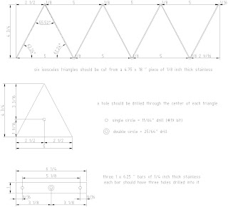
The cardboard "mirror" with paper "triangles" and crossbeams in place (the triangles will eventually be cut out of a 1/8" thick piece of sheet metal, with holes drilled so they can be bolted to crossbeams):


This is the tack welding jig that I built. Ernie made fun of me for it, but I think he must have used it anyway. Either way, the dimensions are correct to 1/16"!


Next, on to the rest of the flotation system...

Sunday, September 19, 2010

float

updated version of float metal fab plans to allow for 1/16" thick cuts:

Sunday, September 12, 2010

tailgate & float

One of my primary non-work activities has been designing a large telescope. This was inspired by reading about William Herschel in the recently paperback-ed "Age of Wonder", and subsequently by buying Dave Kriege's tantalizingly detailed "The Dobsonian Telescope". On the basis of these things, I decided to start constructing one of my own, a 16" alt-az newt reflector, aka Dobsonian. The first stage involves some metal fabrication, and since I (unfortunately) do not know how to weld/drill/cut metal I have had to prepare some documentation to communicate with people who do. The tailgate and float are the first part of this system. I'm shopping around for fabricators now, so hopefully these will actually get made sometime soon! QCAD is very fun too.

1st law of thermodynamics

I'm starting this blog to document the non-work expenditure of energy that I more and more often am engaging in these days. I feel somewhat guilty about this since I always feel like I should work more, and since, according to the first law of thermodynamics, I'm contributing to the eventual heat-death of the universe by expending non-work energy. Regardless, I need somewhere to post stuff so here it is!